Scan pay attention to us
152-6824-5770
- Integrity merchant
- Quality Assurance
- Quality service
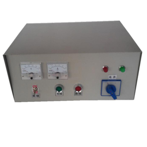
Electromagnetic sucker controller
1. The schematic diagram of electromagnetic chuck is usually divided into power circuit, main circuit, control circuit, signal circuit lighting circuit.
The main circuit refers to the receiving power of power devices shielded electrical appliances. It determines the working current of the electromagnetic sucker, the current is large. The main circuit shall be drawn vertically on the left side of the schematic.
The control circuit is the circuit that controls the main circuit of the complaint system. Signal circuit refers to the circuit representing the main circuit. Lighting circuit refers to the circuit to realize local lighting of electromagnetic chuck grinder. These circuits determine relatively small currents. When drawing the schematic diagram, the control circuit, signal circuit lighting circuit shall be connected between the two-phase power lines, then drawn vertically on the right side of the main circuit. The energy consumption components in the circuit are used for example, the coil of warrior circuit breaker, the signal lamp lighting lamp shall be drawn under the circuit, the contact of the equipment shall be drawn above the energy consumption components.
2. When the circuit is powered on the electrical appliance is affected by external force, the contact position of each electromagnetic chuck is drawn according to the normal position. When analyzing the principle, start the normal position of the contact.
3. The actual outline drawing of each electrical component is drawn, but the unified national standard mark defined by the country / region is adopted. 4. The components of the same electromagnetic chuck are drawn together according to their actual positions, but together in different circuits according to their functions in the circuits, but their functions are interrelated. Marked with similar text.
In addition, in the schematic diagram of electromagnetic chuck, the connection points of interleaving lines with direct electrical discussion should be represented by small black dots, the connection points of interleaving lines without direct electrical discussion should be drawn. The power circuit of the electromagnetic chuck is drawn as a horizontal line. The positive pole of the DC power supply is at the top the negative pole is at the bottom. The power switch shall be placed horizontally.

15268245770

Official account